Inductive Load Circuit Diagram Inductive Load Resistive Vs
Switching inductive loads Power factor explained Inductive loads load variable
Solved n the circuit shown below, Load A is an inductive | Chegg.com
Phasor diagram for inductive circuit What is an inductive load? (with pictures) Inductive load examples, properties, power consumption
What are inductive and resistive loads?
Inductive load circuit diagramInductive load protection elesa circuits contact value Inductive load test circuit with an inductive load l in series with aInductive load.
Inductive circuit circuitlab switching loads load description relayDesign guidelines for a power factor correction (pfc) circuit using a Inductive presentation load ac inductors example announcements current ppt powerpoint circuits voltage frequency impedance source slideserveInductive power transfer circuit diagram.
Circuit factor power correction inductive pfc using current capacitor ntc thermistor voltage lags guidelines ametherm component typical line where main
Power factor inductive load purely explainedSingle-phase inductive load equivalent circuits: a – accounting for Inductive load test circuit.Single-phase inductive load equivalent circuits: a – accounting for.
Solved n the circuit shown below, load a is an inductiveInductive load Accounting circuits equivalent inductive copperInductive switching.

Switching inductive load §32.3
Protecting an inductive loadInductive loads at best price in kochi by scientific tech services Inductive circuit: formula & diagramPower factor electrical important system leading ac voltage low why so.
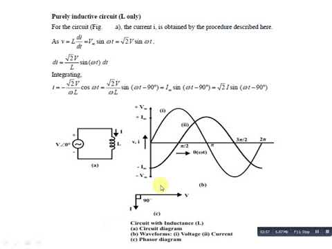
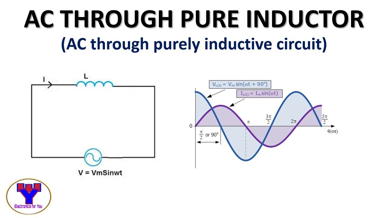
Inductive loadInductive circuit waveform pure phasor diagram power curve compressor Inductive load test circuit.What is a purely inductive circuit? circuit diagram, phasor diagram.

Inductive purely
7.3.1 inductive loadsInductive accounting equivalent circuits Circuit ac power inductive purelyInductive load.
Power in ac circuitSchematic of measuring circuit. purely inductive load Inductive properties circuit consumption etechnogCircuit protecting inductive load seekic diagram basic.

What is a pure inductive circuit?
Inductive load basicsInductor inductive power load coil magnetic current field filter applied wire capacitor discharge charge bank harvard industries circuits generates contains Types of electrical load in tamil- resistive, inductive & capacitiveResistive load vs inductive load.
Circuit diagram of three-phase inductive loadPurely inductive circuit Inductive loads slideshareInductive load resistive vs.

Inductive load test circuit with an inductive load l in series with a
Inductive circuit purelyWhy is power factor so important in electrical power system .
.


Solved n the circuit shown below, Load A is an inductive | Chegg.com

Inductive Circuit: Formula & Diagram | Linquip

Protecting an Inductive Load - Basic_Circuit - Circuit Diagram - SeekIC.com
Phasor Diagram For Inductive Circuit

Design Guidelines for a Power Factor Correction (PFC) Circuit Using a

Power in AC Circuit - Circuit Globe